Modeling and Control of a Mechatronic AeroPendulum
Custom-built mechatronic test platform for system identification, vibration reduction, and feedback control
Overview
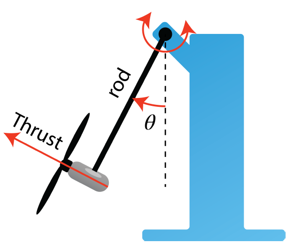
This project presents the design, identification, and control of a custom-built AeroPendulum system. The setup uses a pendulum arm driven by propeller-generated thrust, making it a practical low-cost laboratory platform for testing modeling, system identification, vibration reduction, and feedback control methods.
Problem Statement
The AeroPendulum has nonlinear and oscillatory dynamics. To control its angular position accurately, the system first needs to be modeled and identified from real input-output data. The main challenges are vibration, overshoot, parameter uncertainty, and achieving a stable response on the actual physical hardware.
Solution Approach
- Built a physical AeroPendulum test rig
- Derived the nonlinear mathematical model
- Linearized the model around the operating point
- Collected input-output data at 100 Hz
- Identified the system in the frequency domain using Bode analysis
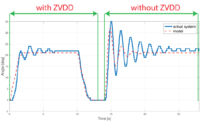
- Designed a ZVDD input shaper to reduce residual vibration
- Tuned a robust PID controller using frequency-domain design
- Validated the controller on the real system using MATLAB/Simulink real-time testing
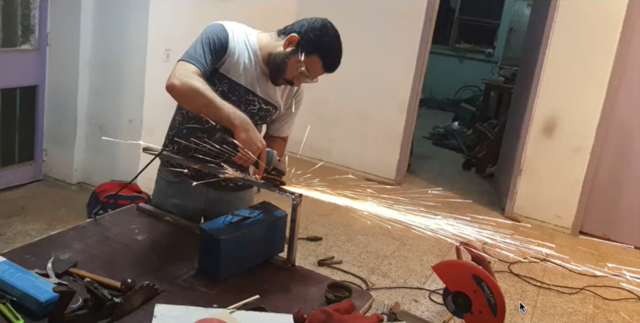
Building the Device
The project started with a custom mechatronic test bench designed for repeatable hardware experiments. Building the physical setup made it possible to move beyond simulation and test identification and control strategies directly on the real system.
Key Features
- Custom-built mechatronic test bench
- Real hardware implementation
- Frequency-domain system identification
- ZVDD input shaping for vibration reduction
- Robust PID control
- MATLAB/Simulink real-time validation
- YouTube demo integration
System Identification
Input-output data collected at 100 Hz was used to identify the AeroPendulum dynamics in the frequency domain. This step established a practical model of the real system and supported both controller tuning and vibration-reduction design.

Results
- Identified the AeroPendulum as a second-order dynamic system
- Reduced overshoot from about 15 degrees to about 4 degrees using ZVDD input shaping
- Designed a PID controller with approximately 62.4 degrees phase margin
- Achieved stable closed-loop angle control on the real system
- Demonstrated disturbance rejection on the actual hardware
Technical Implementation
The system uses a CMPS11 sensor for angle measurement, Arduino Due as the microcontroller, coreless motors for thrust generation, and a Monster Moto Shield as the motor driver. MATLAB/Simulink was used for data acquisition, system identification, controller design, and real-time testing.